10+ timer block diagram
Thus by varying R or C the output pulse width can be varied. This is the working principle of timer IC 555 Timer Circuit.
2
The following figure shows the functional diagram of timer IC 555.

. ACP ID Mapper 105. Reset Manager Address Map and Register Definitions. Features of the Cortex-A9 MPU Subsystem 102.
The 555 Timer IC is available as an 8-pin metal can an 8-pin mini DIP dual-in. The figure down below shows the functional block diagram of 8254 Timer. 49 16-Bit Timer Block Diagrams410 16-Bit Timer Timing Figure 4-15 Timer 4 Block Diagram Figure 4-16 Timer 5 Block Diagram Figure 4-17 Single-Phase PWM Output Timing 16-Bit.
555 Timer IC Pin Configuration. 2100 a and b show the IC 555 Pin. Block Diagram of Intel 8254.
Texas Instruments MSP430x4xx Figure 101. Bistable Mode of operation of 555 timer. As shown in figure IC555 includes two comparators one RS flip-flop and other few discrete components like transistors.
Represented with a block diagram it consists of 2 comparators a flip-flop a voltage. This circuit is simplest one of all 3 modes of operationIn this circit R2 is connected between pin 8 and pin 2 and push button 1 is connected. Off delay timer S_OffDT The general block diagram of the timer In Siemens PLC Where S Set value or signal for the timer.
TV Time Variable. It is used to store time value in. Functional Software Electrical etc.
Functional Description of the Reset Manager 43. A simplified block diagram representing the internal circuitry of the 555 timer is given below with a brief explanation of each of its connecting pins to help provide a clearer. Heres the internal schematics of 555 Timer which consists of 25 transistors 2 diodes and 15 resistors.
Watchdog Timer Block Diagram. Reset Manager Block Diagram and System Integration. IC 555 Pin Diagram.
Ad Templates Tools To Make Block Diagrams. Watchdog Timer Introduction 10-3Watchdog Timer Watchdog Timer Figure 101. Cortex-A9 MPU Subsystem Block Diagram and System Integration 103.
More features are listed in the datasheet. We have already discussed in the beginning that it consists of a total of 3 counters of.
Top 10 Simple Electronics Projects For Complete Beginners

Motorcycle Engine Diagram Pdf Motorcycle Wiring Electrical Wiring Diagram Electrical Diagram

Plc Programming Questions And Answers Programmable Logic Controller Plc Programming Electronic Engineering

Intervention Report Template Awesome Audit Flowchart Examples Cool Photography Police Report Template Process Flow Diagram Data Flow Diagram Drawing Book Pdf

15 2006 Chevy Truck Wiring Diagram Electrical Wiring Diagram 2006 Chevy Silverado Trailer Wiring Diagram
Stm32f107rct6 Microcontrollers Datasheet Pinout Circuit Faq

New Wiring Diagram Ice Maker Diagrams Digramssample Diagramimages Wiringdiagramsample Wiringdiagram Check More Baseboard Heater Diagram Electrical Wiring

Digital Timer 30 Seconds Electronic Stopwatch Gradient Dial Starting Vector Icon Clock Watch Timer Countdown Symbol Vector Il Digital Timer Vector Illustration
2
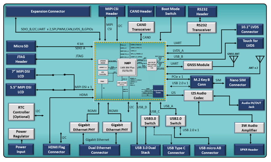
I Mx 8m Plus Pico Itx Sbc Iwave Systems
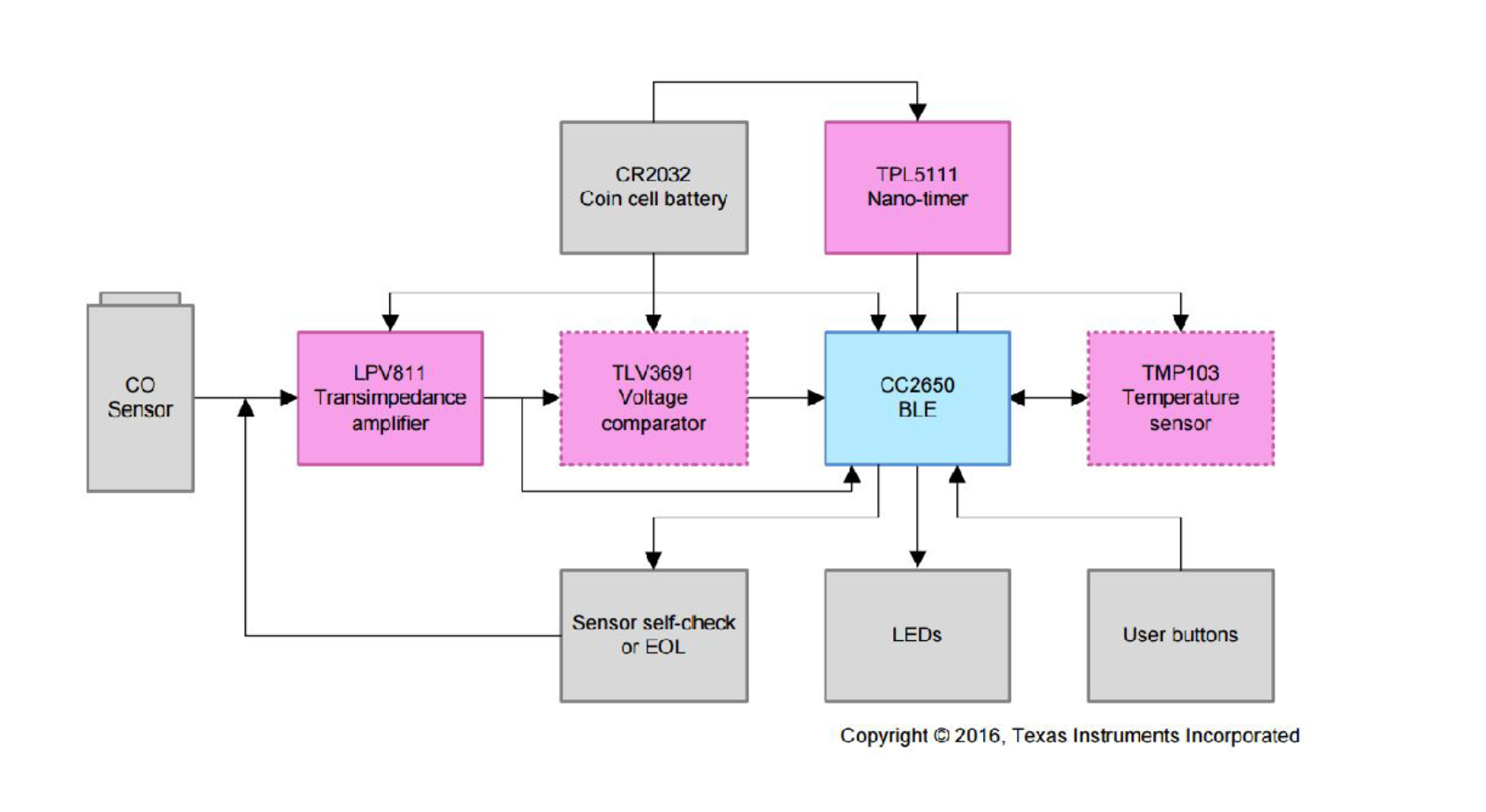
Always On Low Power Gas Sensing With 10 Year Coin Cell Battery Life Reference Design Electronics Lab Com

Closed Loop Tuning Lab Using Moku Go S Pid Controller Liquid Instruments

Pin By Mike Jones On Aquarium Biologi

Diagram Wiringdiagram Diagramming Diagramm Visuals Visualisation Graphical Check More At Https Thebront Diagram House Wiring Electrical Wiring Diagram

Pin On Arch Details Cw
2
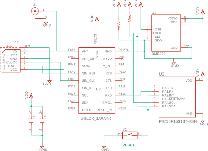
Designing An Nb Iot Device Springerlink